
Or, how to mess with little snakes, my gate, my car, and my neighbors' wifi networks
Oblomov
Yesterday night, after reading a bit of "Oblomov", a book that tells the story of this passive, indecisive and lazy man (is really a whole lot deeper than this, but anyway), a man who needs 200 pages to get out of bed, and even after that, it's not like he stays up for long, I thought about one of the biggest efforts I make every single day, at the very least twice a day: pressing the button that opens the gate of my house to drive out to work, and after 8 hours, re-pressing it to get back in. Who is still pressing buttons in the big 2025?
The Idea
The idea was to automate this enormous effort. But how? The place where I live was built in 1970, it has nothing smart, no home automation or any other cool catchword.
Initially I thought about using a Shelly, but I never used it and didn't feel like waiting for Amazon's 2-day delivery. Then I reminded myself of the 3 ESP-8266s, ancestors of the newer ESP32, which I bought something like 7 years ago. Using these would be perfect!
I then started to think how could I use the ESP8266 to open and close the gate. I had three possibilities
- Connect the ESP to the gate in some way and make it happen
- Consoom and buy some kind of shield or component that enables the board to send stuff on the 433mHz used by the gate remote
- Connect the ESP to an existing remote, and use it to simulate the press of the "Open the gate" button
The first seemed cool, but a bit above my knowledge level. The second was probably the best, but just not in a "cost" and "time" prespective (I really wanted to make everything the same evening, no time to wait for a order of some shitty component from china). At this point the only viable option was the third one.
The remote I normally use every day is around 20€ on Amazon, so cheap enough (sort of) to burn it in case stuff get messy. The hardware seems to be there, so let's explain a bit the architecture of this smoking garbage of an hack with a wonderful chart
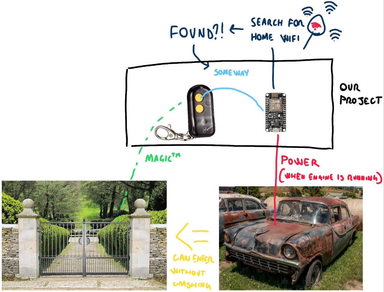
My graphic design skillz are amazing, right? Anyways, here's the flow I imagined:
- I start up the car. The ESP-8266, USB-Powered from the cigar lighter socket (I guess that's how you name it in english), executes its loop
- The ESP continuously keeps scanning the WiFi networks that are in range
- When the home wifi network is in range, open the gate through the remote (how we will do that? IDK yet)
- The gate closes itself after 2/3 minutes, there's no need to use the remote again
- I turn off the car, therefore the cigar lighter socket, therefore the ESP-8266
The big questions are
- will the range of my WiFi network enough to be picked up by the ESP in my car?
- how the hell do I control the remote from the ESP?
We'll answer those questions in the next chapter
The Execution - Hardware stuff
Little disclaimer, I don't know anything about electronics, and probably what I did is wrong, but it works so... you cant tell me nothing. Just kidding, if anyone among the two people who are reading this blog can tell me what to do to improve, please contact me by email, on social or wherever is most convenient for you. Basically, the remote has two buttons, and the upper one is the one i want to press via the ESP. If I use the ESP to close the circuit between the two pins that the button is attached to, the job should be done. So, the first thing I did was de-soldering the small button and soldered two jumper wires, in order to connect them to the board. I thought about putting here a picture of the real thing, but my soldering skills are shit and at the thing, while I'm writing this, is out there in my car and I don't want to go out just for a picture so please, try to understand me.
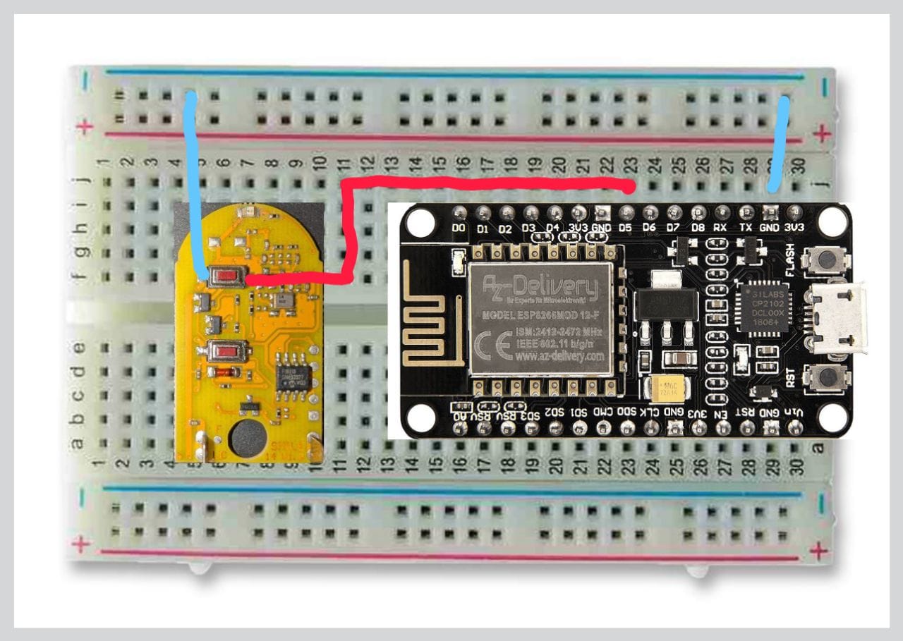
After this, I used a breadboard to connect the two jumpers to the ESP-8266 board. I connected one of the two solder points to the GND pin of the ESP, and the other one to the GPIO number 14, which on my NodeMCU is labelled as D5. Here's a bad schematics of everything.
At this point, the only missing thing is the software, which I actually know a lil bit about. Let's go!
The Execution - Software stuff (very small snakes!)
Even though I always used the Arduino IDE to develop and flash the firmware onto the ESP-8266, this time I wanted to try MicroPython, which is an implementation of Python 3 made to run on microcontrollers and embedded devices where resources are constrained.
ESP-8266 seems to be well supported by MicroPython. First, you need to download and flash the micropython firmware to the ESP-8266. After that we can write our script in python, and copy it to the ESP's internal memory. This will, at startup, run the script automatically. If you want to know more, here's the MicroPython's guide and documentation to ESP-8266.
Flashing the firmware
This step has been really simple: I just downloaded the latest release from the MicroPython releases page, installed the ESPtools Python library, wiped the ESP flash and deployed the firmware.
With the board connected to my computer via the micro USB cable, I executed the following commands:
$ python3 -m pip install esptool
$ esptool.py --port /dev/ttyUSB0 erase_flash
$ esptoo.py --port /dev/ttyUSB0 --baud 115200 write_flash --flash_size detect 0 path/to/micropython/firmware.bin
After that, everything should be ready. A really cool feature of MicroPython is the ability to have a interactive REPL environment accessible via the USB serial interface. This is really useful to check if the firmware flashing procedure went good, and to quickly prototype and debug the code that has to be executed by the ESP. You can access the serial REPL using picocom
$ picocom /dev/ttyUSB0 -b115200
Writing the loop
The script we need to write in order to make everything work is quite simple:
- Initialize the digital output pin connected to the gate's remote
- Initialize the ESP's WLAN client
- Loop forever
- Get a list of available WLAN networks
- Check if there's a network with the same SSID of our home one
- If it is found:
- Set the pin to OFF (I really don't have idea why it's inverted) in order to emulate the press of the button
- Wait for a bit
- Set the pin to ON to emulate the release of the button
Here's the complete code. There's a lot of room for improvement, I know, but it works
Loading the script
Loading the micropython script on the board is really trivial: just install the Adafruit MicroPython Tool with the following command
$ python3 -m pip install adafruit-ampy
And then, in the same folder where you have the script, load it on the board by running
$ ampy --port /dev/ttyUSB0 put main.py
That's it!!
It works?!!
Now, I would really love to show how well this works, but I'm not really comfortable to put videos of my house on the whole internet. But let me say that it works really well, both in and out the gate. In the morning, when I start up the car, by the time I fasten my seatbelt the gate is already open. When I came back home, I almost enter directly in my garden without slowing down, because the moment I drive down the driveway, the gate is already open. In order to speed things up even more, I thought about putting inside the script the WiFi network of my neighbors that are on the main street, in order to make the ESP press the remote even earlier, but I don't really know how far the remote signal to the gate can travel.
Anyway, that's it for today's adventure. I'll write another post or update this one if I'll make significant changes to this project. What I would really like to do is to 3d print an enclosure for the ESP and the remote, but I'll see.
Thank you for your time and happy hacking!